
Complete Street Light Solutions for Urban & Commercial Projects
Our complete street light solutions combine appearance design, LED lighting(opens in new tab) performance, structural wind resistance, and foundation engineering for urban roads, commercial developments, and government projects(opens in new tab). From common street lighting problems and solutions to customized engineering requirements, we provide a complete technical package from design to installation.
01
Appearance Design
02
Lighting Design
03
Wind Resistance
04
Foundation Design
Solution Module
Decorative Street Lighting Solutions & Appearance Design
Our decorative street lighting solutions combine architectural aesthetics with structural durability, corrosion resistance, and project-specific visual identity. Pole shapes , luminaire styles, colors, decorative patterns, and smart accessories can all be customized for streets, parks, plazas, resorts, and commercial developments.
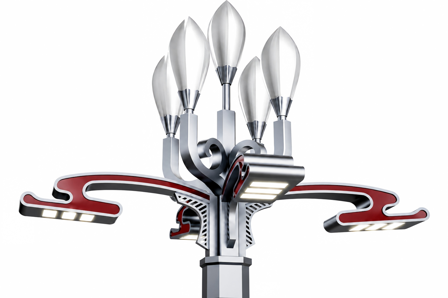
Design Dimensions
Pole Profile & Form Factor
Choose conical, straight, cylindrical, or decorative poles from 6 m to 15 m. Each design can be engineered as part of our street light solutions according to road width, installation environment, mounting height, and architectural requirements.
Surface Treatment & Finish
Hot-dip galvanizing and RAL powder coating provide long-term corrosion protection for outdoor street light solutions. Salt-spray resistance of ≥1,000 hours and UV-stable finishes are available for tropical, coastal, desert, and high-humidity environments.
Luminaire Housing Style
Modern slim LED luminaires, traditional lanterns, decorative fixtures, and integrated solar lights are available for different decorative street lighting solutions. IP65-IP68 die-cast aluminum housings support reliable outdoor operation, while OEM branding, colors, and logo engraving are available for customized projects.
Compliance & Certification
Our engineered street light solutions can be designed around IEC requirements, applicable CE and RoHS requirements, and local municipal specifications. CAD drawings, 3D renderings, technical data sheets, and supporting documents can be prepared for project bidding and technical approval..
Customization Options
Solution Module
LED Street Lighting Solutions & Photometric Design
Our LED street lighting solutions use professional photometric design and DIALux simulation to improve road visibility, illumination uniformity, energy efficiency, and project compliance. Each lighting layout is optimized according to road classification, pole height, spacing, luminaire power, and required lux levels.
Photometric Performance
High-efficiency LEDs and optimized optics allow our LED street lighting solutions to deliver the required road illumination with lower energy consumption and reduced maintenance requirements.
Efficacy
≥ 160 lm/W
CRI
≥ 70
CCT
3000-6500K
Lifespan
≥ 50,000 h
Road Classification
Lighting levels are engineered according to road type, traffic conditions, project requirements, and applicable local standards, helping solve common street lighting problems and solutions related to insufficient illuminance, poor uniformity, glare, and excessive energy use.
Smart Dimming & Control
Smart controls can be integrated into our LED street lighting solutions for remote monitoring, scheduled dimming, motion-based control, and real-time fault detection. 4G/5G, NB-IoT, DALI, and sensor-based control options help reduce unnecessary energy consumption and simplify maintenance.
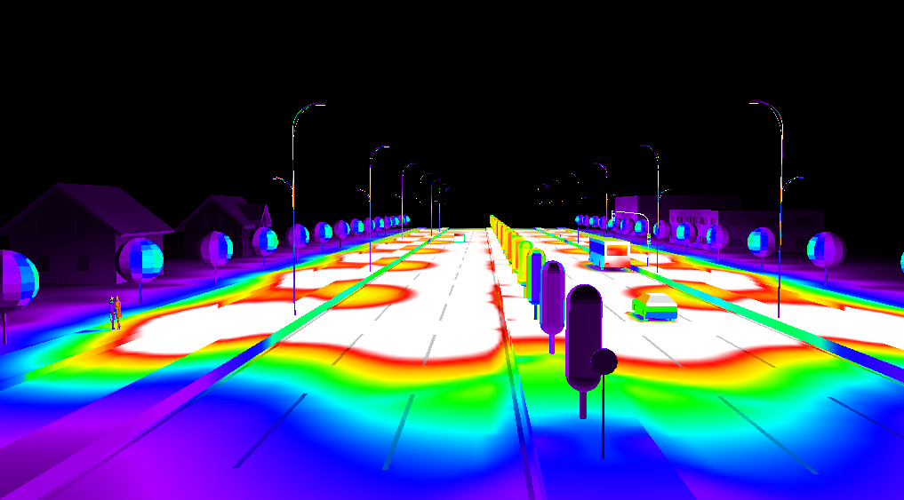
DIALux Simulation Output
DIALux simulations support our street light solutions with road illuminance calculations, false-color analysis, uniformity evaluation, pole spacing optimization, and luminaire selection before project installation.
Design Deliverables
Solution Module
Wind-Resistant Pole Design for Street Light Solutions
Structural engineering is a critical part of reliable street light solutions. Pole dimensions, wall thickness, material grade, weld design, anchor bolts, and foundations are evaluated according to project wind speed, terrain, luminaire area, and installation environment.
Wind Load Calculation
Wind-load calculations consider applicable engineering standards, local building requirements, design wind speed, pole height, projected luminaire area, and site conditions. These calculations help ensure long-term structural reliability for project-specific street light solutions.
Pole Material Specifications
High-strength Q345B/S355 steel is available with precision welding and optional non-destructive testing. Pole diameter, taper ratio, wall thickness, and reinforcement are calculated according to pole height, equipment load, and design wind conditions.
Safety Factors & Validation
Pole structures can be verified using FEA, bending-moment calculations, deflection checks, and third-party testing where required. Engineering documentation can be supplied according to project specifications and tender requirements.
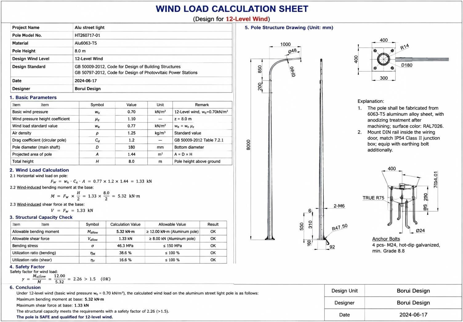
Structural Analysis Diagram
Wind load vectors, bending moment distribution, and anchor bolt layout
Wind-Resistance Engineering Process for Street Lighting Projects
Site Wind Assessment
Regional wind speed data collection. Terrain category classification (open / suburban / urban). Return period analysis (50-year design wind).
Load Combination Analysis
Wind pressure × drag coefficient × projected area. Combined with self-weight, luminaire load, and solar panel load. Dynamic gust factor applied.
Section Optimization
Iterative FEA to optimize wall thickness, taper ratio, and weld joint positions. Material savings balanced against structural performance targets.
Certification & Documentation
Structural calculation report, material test certificates, and factory inspection records provided for government project compliance.
Solution Module
Foundation Engineering for Street Light Solutions
Reliable street light solutions require foundations designed around pole height, wind load, equipment weight, anchor-bolt configuration, and local soil conditions. We provide foundation engineering for standard concrete foundations, precast systems, and deep-pile applications.
Concrete Anchor Foundation
Cast-in-place reinforced concrete foundations provide a practical option for most urban and commercial street light solutions, with anchor-bolt cages engineered according to pole size, wind load, and soil bearing capacity.
Precast Foundation Cage
Prefabricated foundation and anchor-bolt systems can shorten on-site installation time while improving dimensional consistency and construction efficiency for large-scale street lighting projects.
Deep Pile Foundation
Deep-pile foundations are available for soft soil, high groundwater levels, coastal areas, and high-wind locations where increased uplift and lateral-load resistance are required.
Foundation Engineering Process
Key Design Parameters
Overturning Moment
M = F × H
Wind force × effective height
Bearing Capacity
≥ 150 kPa
Minimum allowable soil bearing
Anchor Bolt Torque
Per EN 1993
Eurocode bolt preload standard
Settlement Limit
≤ 25 mm
Total allowable settlement
Street Light Solution Engineering Deliverables
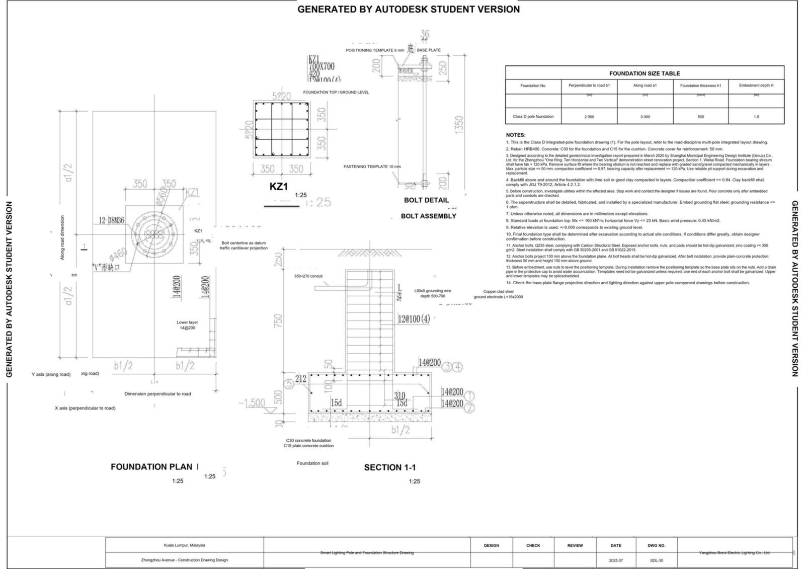
Foundation Cross-Section
Anchor bolt cage, rebar layout, and soil stratification diagram
Soil Condition Quick Reference
Street Light Solutions
FAQ & Expert Answers
Everything you need to know about street lighting problems and solutions, LED street lighting solutions, and how Jinborui Electric delivers reliable solar-powered infrastructure for projects worldwide.
Street Light Solutions -- General Questions
What are the most effective street light solutions for rural and off-grid areas?
Solar-powered street light solutions are the most cost-effective and practical choice for rural, off-grid, and developing-region projects. They require no grid infrastructure, eliminate ongoing electricity costs, and can be installed in remote locations without trenching or cable runs.
Jinborui Electric specializes in integrated all-in-one solar street lights that combine the solar panel, lithium battery, LED chip, and intelligent controller into a single unit -- dramatically reducing installation time and civil engineering costs. Our systems are designed for reliable 3-5 rainy day autonomy, making them a proven street light solution across Africa, Southeast Asia, and South Asia.
How do I choose the right street light solution for a government or World Bank-funded project?
Government and multilateral-funded infrastructure projects typically require compliant documentation, technical specifications, and DIALux lighting simulation reports. The right street light solution must meet local lux standards, pole height requirements, and road classification criteria.
Jinborui Electric has supplied products for 200+ government projects and World Bank-funded programmes. We provide full bidding document support, CAD drawings, DIALux simulations, and cost optimization proposals -- all aligned to international procurement standards. Our team works directly with engineering contractors to ensure smooth tender qualification and product compliance.
What types of street light solutions does Jinborui Electric offer?
Our product range covers every major street lighting application:
- •Solar Street Lights -- all-in-one and split-type designs for highways, residential roads, and rural areas
- •LED Street Lighting Solutions -- high-efficacy LED modules for grid-powered urban and municipal roads
- •4G/5G IoT Smart Lighting -- remotely managed networks with dimming, fault detection, and energy analytics
- •High Mast Lights -- for ports, stadiums, interchanges, and large open areas
- •Photovoltaic Energy Storage Systems -- for hybrid and independent microgrid applications
All products support OEM/ODM customization with a 27,000㎡ factory and 50,000-set annual capacity.
Can street light solutions be customized for OEM/ODM projects?
Yes. Jinborui Electric operates as both a standard product manufacturer and a full-service OEM/ODM partner. We support custom housing designs, wattage configurations, color temperatures, pole bracket angles, branding, and packaging.
Our engineering team provides complete design drawings, sample prototyping, and pre-shipment quality testing. Whether you need a unique aesthetic for a municipal streetscape or a ruggedized design for desert environments, our R&D team can develop a street light solution that meets your exact project specifications.
Street Lighting Problems and Solutions
What are the most common street lighting problems and how are they solved?
The most frequently encountered street lighting problems and solutions in infrastructure projects include:
❌ Problem: Insufficient illumination or uneven light distribution
✅ Solution: Proper road classification analysis with DIALux simulation to determine optimal pole spacing, mounting height, and luminaire wattage -- ensuring uniform lux levels across the entire carriageway.
❌ Problem: High electricity costs from legacy HPS or metal halide lamps
✅ Solution: Retrofit with LED street lighting solutions or solar-integrated systems, reducing energy consumption by 50-70% and eliminating grid dependency entirely in off-grid installations.
❌ Problem: Frequent lamp failures and high maintenance costs
✅ Solution: LED luminaires with 50,000+ hour rated lifespan and smart IoT fault-detection systems that alert maintenance teams before full failure, minimizing downtime and reactive repair costs.
❌ Problem: Power grid unavailability in rural or developing regions
✅ Solution: Standalone solar street light solutions with lithium iron phosphate (LiFePO4) battery storage providing 3-5 days of autonomy without any grid connection required.
❌ Problem: Light pollution and wasted upward illumination
✅ Solution: Optical-grade LED lenses engineered for IES Type II, III, and IV road distributions, directing 95%+ of lumens onto the road surface with minimal glare and spill.
Why do solar street lights sometimes fail or underperform, and what is the solution?
Solar street lighting problems most commonly stem from undersized system design -- particularly batteries and solar panels that are too small for the local irradiation levels and intended working hours. Additional causes include low-quality lithium cells that degrade rapidly, incorrect panel tilt angles, or poor waterproofing leading to circuit corrosion.
Our solutions address each root cause:
- •Site-specific solar irradiation data analysis before system sizing
- •Grade-A LiFePO4 battery cells with 2,000+ cycle lifespan and BMS protection
- •IP65/IP66 rated housings and sealed junction boxes for all climatic conditions
- •Monocrystalline PERC solar panels with 22%+ conversion efficiency
How do I solve the problem of street lights not turning on at night or turning off early?
This is one of the most reported street lighting problems and solutions depend on identifying whether the cause is a battery capacity issue, controller configuration, or panel shading.
Common diagnostic steps and fixes:
- 1.Battery SOC too low: The battery is undersized for the working hours required. Solution: upsize battery or reduce working wattage via time-segmented dimming (e.g., 100% at dusk, 50% after midnight).
- 2.Incorrect controller settings: Time-zone or timer misconfiguration. Our MPPT controllers are pre-programmed and GPS-enabled for automatic dusk-to-dawn detection.
- 3.Panel shading: Trees, buildings, or debris blocking the panel reduce daily charge input. Solution: re-evaluate installation site and orient panel toward maximum solar exposure.
For IoT-enabled systems, real-time remote monitoring alerts operators instantly when a unit's battery level or working status deviates from normal parameters.
How can street lighting be made more resilient in extreme weather conditions?
Extreme climate presents significant street lighting problems. Solutions require engineering at both the product and system design level:
- •High wind zones: Wind-resistance-rated poles (up to 60m/s) with structural calculations; aerodynamic luminaire housings reduce drag loading.
- •Extreme cold (below -20°C): Low-temperature LiFePO4 batteries with thermal management modules maintain performance in arctic climates.
- •Desert heat and sandstorms: Die-cast aluminum housings with IP66 and IK09 ratings protect optical and electronic components from dust ingress and impact.
- •High humidity and coastal salt air: Marine-grade corrosion-resistant surface treatments and sealed electronics compartments extend operational lifespan to 10+ years.
LED Street Lighting Solutions
What are the advantages of LED street lighting solutions over traditional HPS lamps?
LED street lighting solutions deliver measurable performance advantages over legacy High Pressure Sodium (HPS) and metal halide technologies across every key metric:
⚡ Energy Efficiency
LED efficacy of 160-200 lm/W vs. HPS at 80-120 lm/W -- delivering 50-70% energy savings for equivalent road illumination levels.
⏱ Lifespan
50,000+ hour LED lifespan versus 15,000-24,000 hours for HPS, reducing lamp replacement frequency by 3-4 times.
🎨 Light Quality
CRI 70-80+ LED white light dramatically improves nighttime visibility and color recognition compared to the yellow-orange HPS spectrum.
🌱 Environmental Impact
No mercury content, reduced CO₂ emissions, and compatibility with solar street light solutions for fully carbon-neutral road lighting.
What wattage LED street light do I need for my road type?
Wattage selection for LED street lighting solutions depends on road width, pole height, pole spacing, and required average illuminance (lux). As a general reference:
| Road Classification | Road Width | Pole Height | LED Wattage |
|---|---|---|---|
| Village / Pathway | 4-6 m | 5-6 m | 20-30 W |
| Residential / Secondary | 6-9 m | 6-8 m | 40-60 W |
| Collector / Urban | 9-14 m | 8-10 m | 80-120 W |
| Arterial / Highway | 14-20 m | 10-12 m | 150-200 W |
| High Mast / Expressway | 20 m+ | 20-40 m | 400-2000 W |
Note: These are indicative values. Jinborui Electric provides free DIALux simulation reports for precise wattage and pole-spacing confirmation.
What is a 4G/5G IoT smart LED street lighting solution and does my project need it?
Smart LED street lighting solutions integrate 4G/5G cellular communication modules into each luminaire, enabling a centralized management platform to monitor and control every light point individually across an entire city or district.
Key capabilities include:
- •Remote on/off switching and time-programmed dimming schedules
- •Real-time fault alerts reducing emergency maintenance response time
- •Energy consumption analytics per luminaire for billing verification
- •Dynamic dimming in response to traffic sensors or weather events
Smart LED street lighting solutions are ideal for municipal PPP projects, smart city initiatives, and any scheme where operational cost reduction and measurable KPI reporting are required by funders or government authorities. Contact us to discuss platform integration requirements for your specific project scope.
What certifications should LED street lighting solutions carry for international projects?
International procurement for LED street lighting solutions typically requires one or more of the following certifications depending on the destination market:
CE Marking
European Union markets
ETL / UL
North American markets
IEC 60598 / IP65+
International luminaire safety
RoHS Compliance
Hazardous substances restriction
UN38.3 Battery
Lithium battery transport safety
ISO 9001
Quality management system
Contact our team to confirm which certifications are available for your target market or to initiate an OEM certification process for specific regional requirements.
How long is the warranty on LED street lighting solutions from Jinborui Electric?
Jinborui Electric provides industry-standard warranty coverage designed to support long-term infrastructure projects:
- •LED Luminaires: 3-5 year warranty covering LED module, driver, and housing defects
- •Solar Panels: 10-year product warranty, 25-year linear power output guarantee
- •LiFePO4 Batteries: 3-year warranty with capacity guarantee for the first 2,000 cycles
- •Spare Parts: Guaranteed spare parts supply for a minimum of 5 years post-delivery
For large-scale government projects, extended warranty terms and on-site service agreements can be negotiated. Our after-sales team provides remote diagnosis support and coordinates warranty replacement dispatch from our Yangzhou factory.
Procurement, Shipping & Support
What is the minimum order quantity (MOQ) and typical lead time for street light solutions?
MOQ varies by product type and customization level. For standard catalog products, the MOQ is typically 10-50 units, which supports sample evaluation for project tendering. For OEM/ODM projects with custom tooling, minimum orders are discussed based on product complexity.
Standard lead times from order confirmation:
- •Samples: 7-15 business days
- •Standard production orders: 25-35 days
- •Large-volume government projects (5,000+ units): 45-60 days with phased delivery available
Our 50,000-set annual production capacity ensures we can fulfill urgent large-scale street light solution orders without compromise on quality or timeline.
Does Jinborui Electric provide installation guidance and technical training for street light solutions?
Yes. Jinborui Electric provides comprehensive installation and technical support as part of our end-to-end street light solution service:
- •Installation Manuals: Detailed multilingual installation guides and wiring diagrams ship with every order
- •Video Training: Step-by-step installation and commissioning videos available for all product lines
- •Remote Technical Support: WhatsApp, email, and video call support during and after installation
- •On-Site Training: Available for large government contracts -- our engineers can conduct in-country training for local installation teams
- •Construction Planning: Pre-project site assessment support and construction sequence planning assistance
Which countries has Jinborui Electric supplied street light solutions to?
Over 12 years of operation, Jinborui Electric has exported street light solutions to 30+ countries across five continents. Our experience spans a wide range of climates, regulatory environments, and project procurement models:
🌍 Africa
Nigeria, Kenya, Ghana, Tanzania, Ethiopia
🌏 Southeast Asia
Philippines, Vietnam, Cambodia, Myanmar
🌏 South Asia
Bangladesh, Pakistan, Nepal, Sri Lanka
🌍 Middle East
Saudi Arabia, UAE, Iraq, Yemen
🌎 Latin America
Brazil, Colombia, Peru, Ecuador
🌍 Central Asia
Kazakhstan, Uzbekistan, Kyrgyzstan
We have deep experience with World Bank, ADB, and government-direct procurement frameworks across all these regions, ensuring products arrive with the correct documentation, certifications, and shipping terms for smooth customs clearance.
Still Have Questions About Street Light Solutions?
Our engineering team has solved street lighting problems and solutions across 30+ countries. Get a free consultation, DIALux simulation, or product quote for your project.
Get Expert Advice
Factory
Guoji Industrial Park, Yangzhou,
Jiangsu Province, China
Get Complete Street Light Solutions for Your Project
From decorative street lighting solutions and professional LED street lighting solutions to structural calculations and foundation engineering, we provide a complete project package tailored to your specifications, local standards, and bidding requirements.